Interfaces and Connections
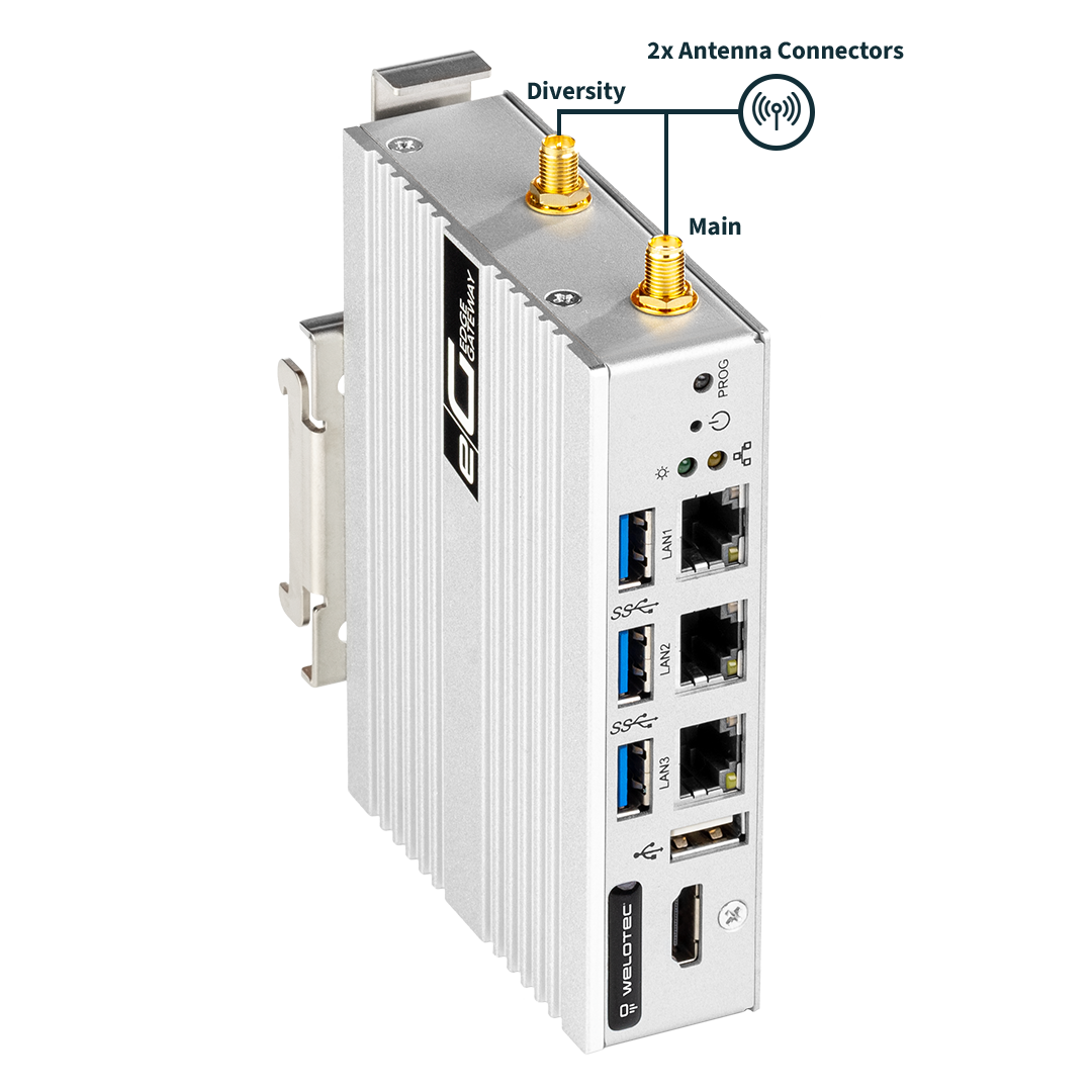
EG400 Mk2 & EG500 Mk2
EG400 Mk2 |
EG500 Mk2 Headless |
EG500 Mk2 |
|---|---|---|
|
|
|
|
|
|
|
|
|
|
|
|
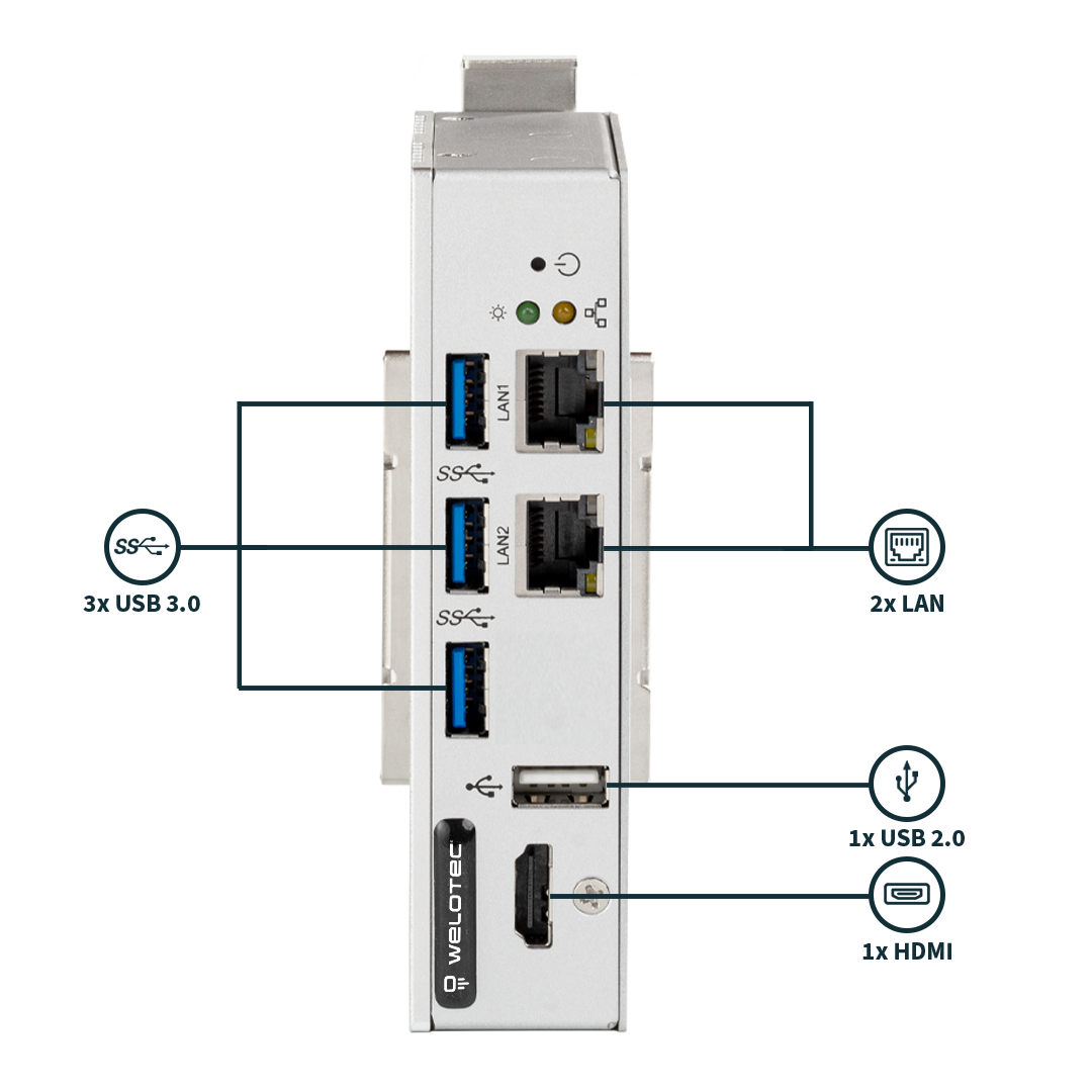
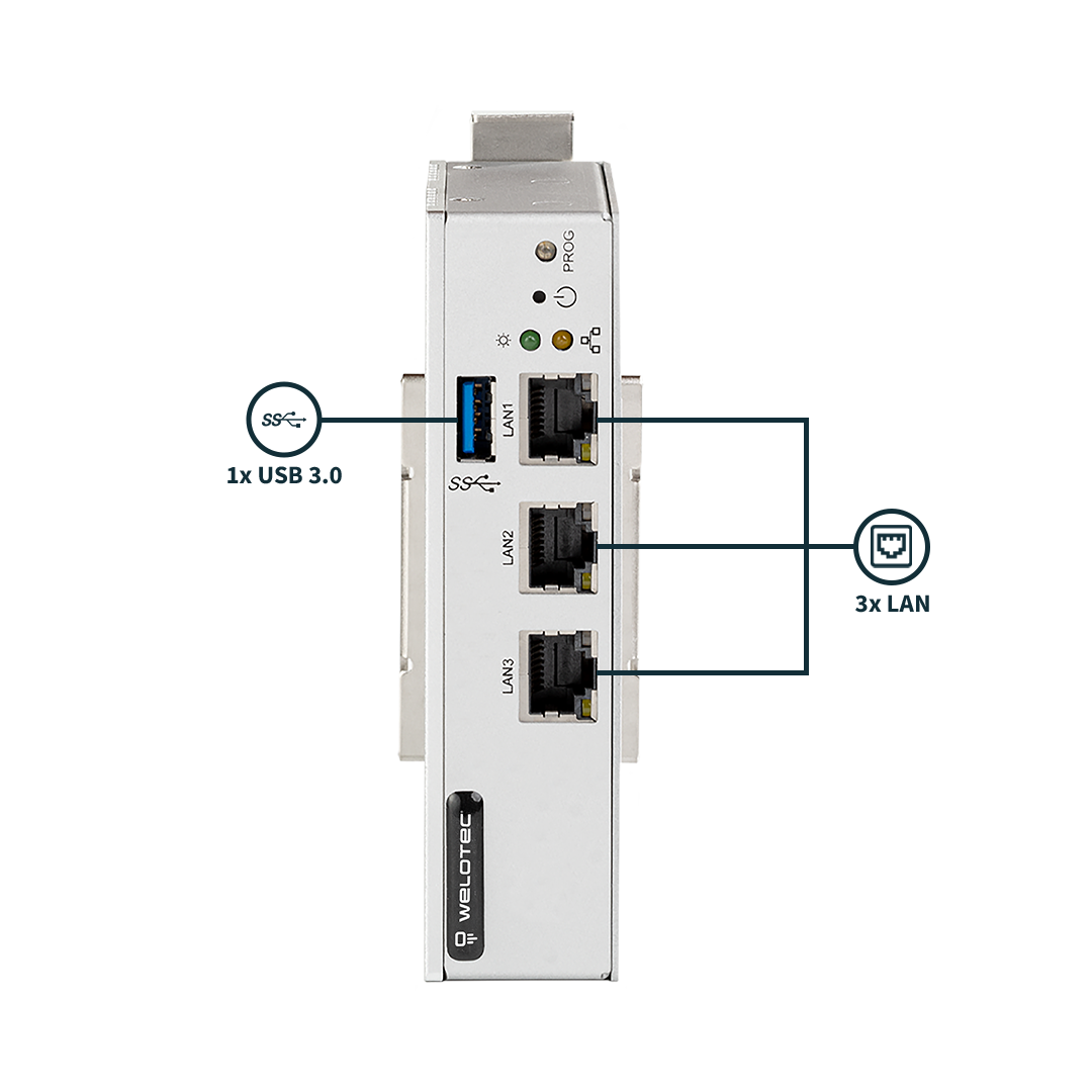
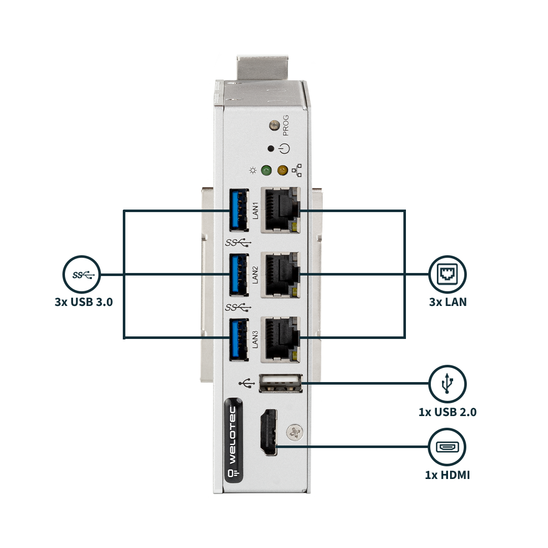
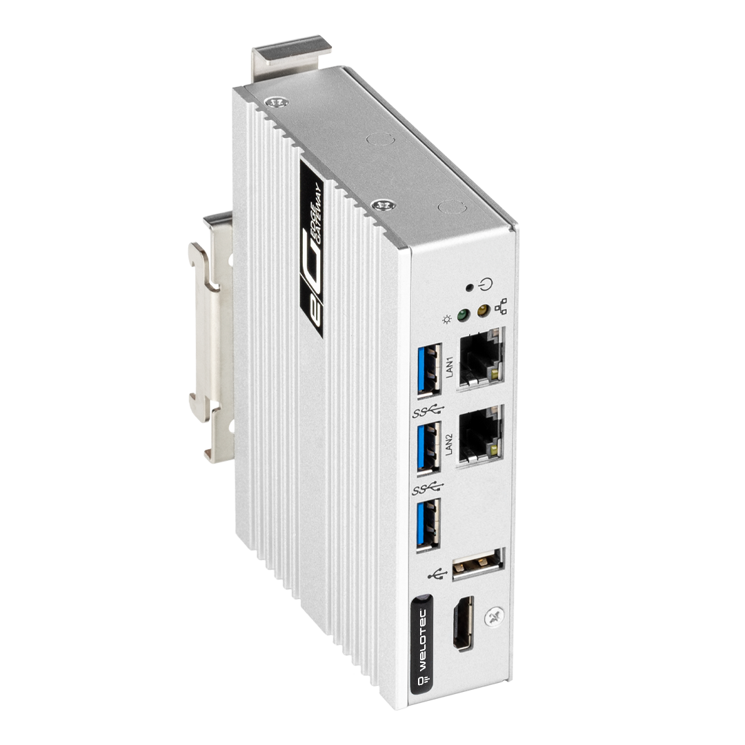
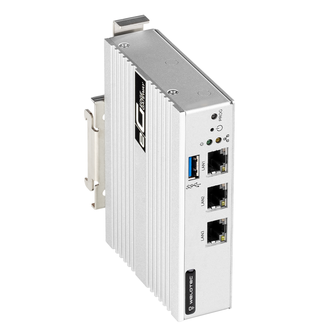
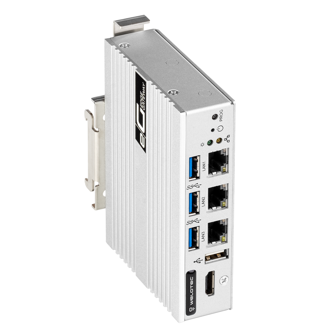
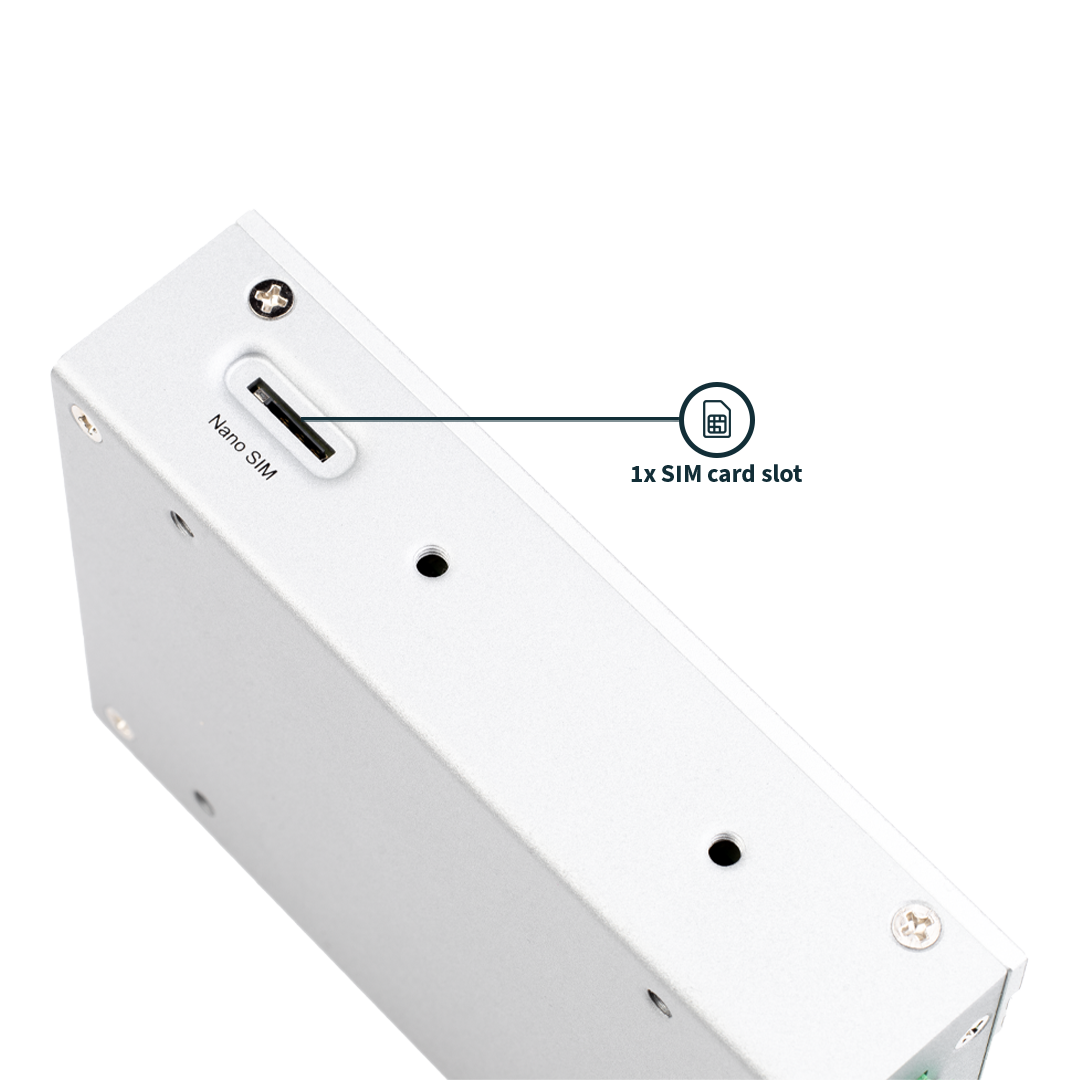
EG500 Mk2 (with optional Radio Module)
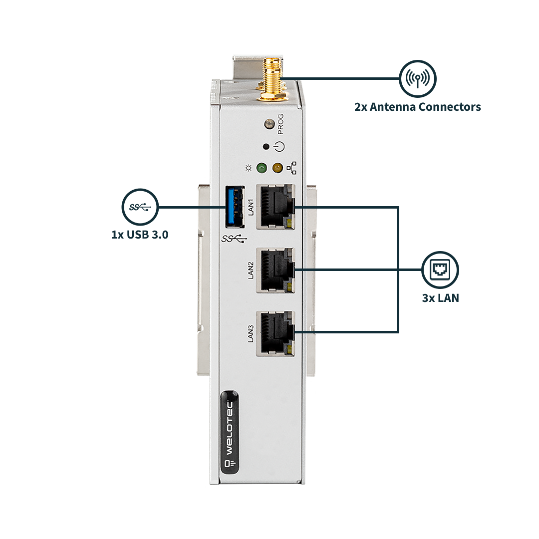
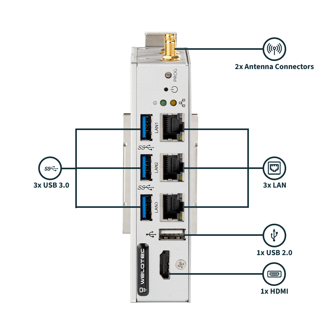
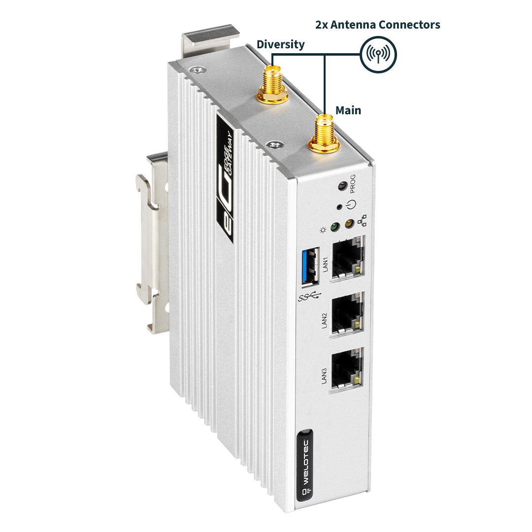
EG500 Mk2 Headless |
EG500 Mk2 |
|---|---|
|
|
|
|
|
|
|
|
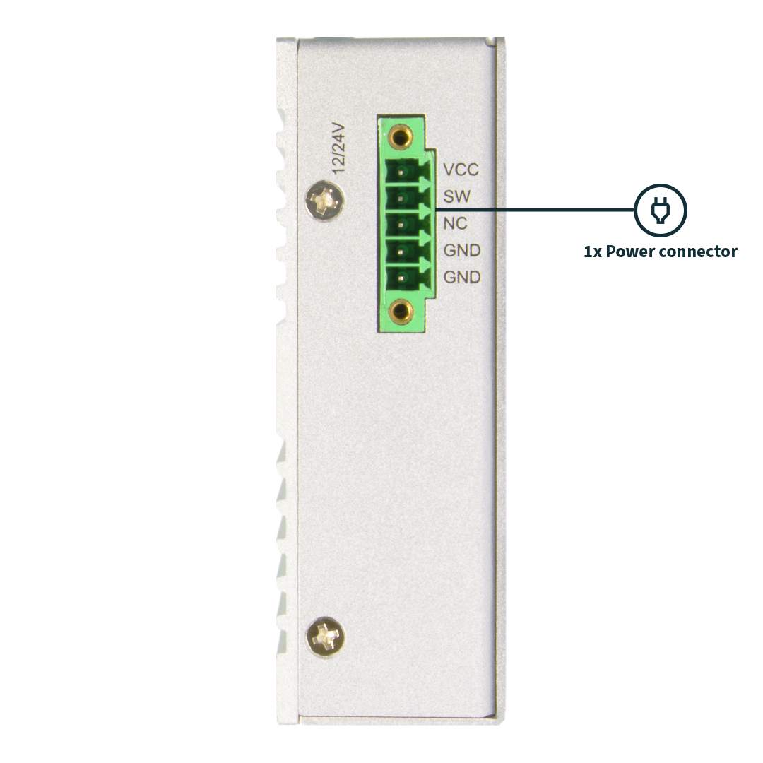
Connecting an external Power Switch
The schematis is showing how connect an external Power Switch to the Power Connector
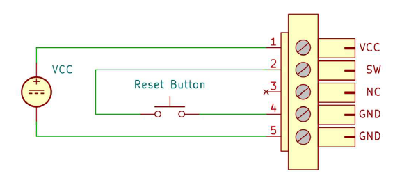
⚠️ Please ensure no external voltage is applied to SW! This could cause damage.
Pin |
Description |
|---|---|
Pin 0 – VCC |
V+ 12-24V |
Pin 1 – SW |
External power switch |
Pin 2 – NC |
Not connected |
Pin 3 – GND |
Ground |
Pin 4 – GND |
Ground |
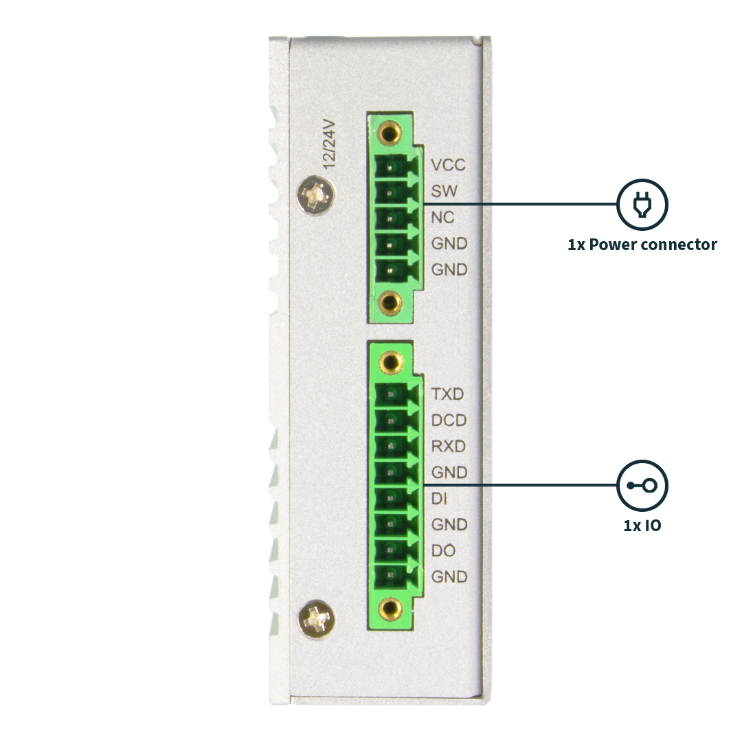
Serial Interface and DIO Connection
RS232 Interface
Pin |
Description |
|
|---|---|---|
Pin 1 |
TXD |
RS232 Transmit Data |
Pin 2 |
DCD |
Data Carrier Detect |
Pin 3 |
RXD |
RS232 Receive Data |
Pin 4 |
GND |
Ground |
Digital IO
Pin |
Description |
|
|---|---|---|
Pin 5 |
DI |
Digital Input |
Pin 6 |
GND |
Ground for DI |
Pin 7 |
DO |
Digital Ouput |
Pin 8 |
GND |
Ground for DO |
DI input range is +12 … 24V DC, default pull up 10KΩ to +3.3V
DO output voltage is railed from device supply voltage, maximum current is 2A